
Transparent powder coating is a type of coating widely used in industrial and home decoration…
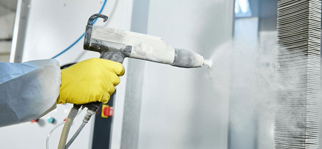
4 Setups to Reach 90% Powder Coating Transfer Efficiency
You might have a spray gun claiming a “99% powder coating transfer efficiency,” yet actual tests show it only climbing from 60% to 75%, with the rest drifting into the filter cartridges. The root cause usually isn’t the gun itself, but a lack of alignment among four key parameters: voltage, grounding, spray distance, and atomization. Adjust these four settings according to the guidelines below, and boosting transfer efficiency from 60% to 90% becomes the norm.
I. Clarifying “Powder Transfer Efficiency”
Powder coating transfer efficiency — also known as powder utilization rate — measures the ratio of powder actually deposited as a coating on the workpiece versus the total amount sprayed. The industry average hovers between 55% and 70%; in other words, for every 100 kg of powder purchased, 30–45 kg drifts away, gets trapped in the filters, or fails to adhere.
Traditional air spraying fares even worse, with transfer efficiencies of only 30%–50%. Switching to electrostatic powder coating offers a theoretical recovery rate exceeding 95%, provided the parameters are correctly matched.
What does raising transfer efficiency from 60% to 90% mean for a typical small-to-medium production line? Based on an annual output of 500,000 units and a powder consumption of 120g per unit, you save approximately 18 tons of powder annually. At an average price of 85 RMB/kg, this cuts annual material costs by about 1.5 million RMB. This kind of saving is far more tangible than simply switching to the latest “viral” spray gun.
II. Setting Voltage to 60–80kV: The Key to Doubling Transfer Efficiency for Simple Parts
High-voltage electrostatics are the source of the powder’s charge. A negative high voltage of 60–100kV is applied at the spray gun’s electrode, giving powder particles a negative charge so they are attracted to the grounded (positive) workpiece. If you fail to master these electrostatic forces, even the most expensive spray gun is useless. Higher voltage is not necessarily better. Technical documentation from various equipment manufacturers indicates that epoxy/polyester powders achieve peak adhesion efficiency in the 60–80 kV range, while polyurethane/acrylic powders are more sensitive and perform better at 50–80 kV. Exceeding 100 kV can trigger “back-ionization”—where powder particles repel each other, resulting in an “orange peel” finish and a drastic drop in adhesion.
For complex parts (featuring recesses or dead zones), voltage should be reduced to 50–70 kV to prevent the “Faraday cage effect” from trapping the charge on the outer surface; conversely, simple flat parts can be processed at 70–90 kV to enhance adhesion. When humidity exceeds 60%, air conductivity increases, requiring a voltage reduction of 5–10 kV to prevent leakage; conversely, if humidity falls below 40%, powder tends to clump, so voltage may be slightly increased.
III. Grounding resistance must be <4 Ω; this is the bottom line.
For a workpiece to act like a magnet for powder, proper grounding is essential. If grounding resistance is too high, current cannot flow effectively; consequently, the powder fails to adhere regardless of its charge level, and issues such as arcing or abnormal corona discharge may occur at the spray station. Standards from multiple equipment manufacturers clearly specify that grounding resistance should ideally be ≤1 Ω; in actual production, ≤4 Ω is acceptable, with a maximum limit of 5 Ω.
How significant are grounding issues among coating defects? Industry research shows that approximately 25% of coating defects stem from grounding problems—a figure that translates to an additional $740,000 in annual rework costs for a single factory. The checklist is concise, but every step is critical:
① Use a grounding resistance tester to measure resistance from the hanger to the ground terminal; investigate immediately if it exceeds 4 Ω;
② Ensure grounding wires are free of looseness, breakage, or oxidation, and that the contact area at connection points is ≥70%;
③ Ensure a conductive path exists between the hanger and the workpiece; avoid insulating gaskets or excessive gaps;
④ Ensure workpiece surfaces are free of insulating coatings (such as paint or oil residue); perform sanding or chemical degreasing if necessary;
⑤ Maintain workshop humidity between 40% and 60%; excessively low humidity promotes static buildup, while excessively high humidity affects other process parameters.
Non-conductive workpieces (such as plastics) require conductive modification before coating—either by applying a conductive primer (e.g., conductive epoxy paint) or using flame treatment to enhance surface conductivity; otherwise, the powder will not adhere, regardless of voltage adjustments.
IV. Spray distance: 150–250 mm; atomization air pressure: 0.3–0.6 MPa
If the spray gun is too close to the workpiece, powder rebound or dielectric breakdown occurs; if it is too far away, adhesion efficiency drops sharply. The industry-standard “sweet spot” is 150–250 mm, though this can be fine-tuned based on specific powder characteristics: high-resistance powders (volume resistivity >10¹⁰ Ω·cm) require high voltage and a shorter spray distance, whereas low-resistance powders (<10⁹ Ω·cm) require a greater distance to prevent excessive ionization.
Atomization air pressure must also be adjusted according to the powder type. The recommended range is 0.3–0.6 MPa: excessive pressure scatters the powder into overly fine particles that drift into the recovery unit, while insufficient pressure leads to poor atomization, resulting in coarse particles that compromise coating uniformity. Current settings should be 0.5–1.5 mA for manual guns and 1–2 mA for automatic guns; exceeding 3 mA increases the risk of electrical discharge.
V. Powder resistivity determines the voltage setting
Different powders vary significantly in their voltage tolerance. Experimental data from a coating equipment manufacturer indicates the following:
• Epoxy resin: 60–80 kV; exceeding this threshold results in an efficiency loss of approximately 25%.
• Polyester hybrid: 70–90 kV; exceeding this threshold results in a loss of approximately 30%.
• Ultrafine powders/special formulations: Follow the manufacturer’s recommended range; do not simply apply standard parameters.
Powder resistivity should be measured using a resistivity meter (e.g., Keithley 6517B). High-resistance powders retain charge, leading to strong adhesion but a risk of cracking if the coating becomes too thick; low-resistance powders dissipate charge quickly, resulting in uniform thin coatings but weaker adhesion. Measuring resistivity provides the necessary basis for selecting the correct voltage.
VI. Five Common Pitfalls: Stumbling into Just One Can Halve Your Powder Deposition Rate
① Using reclaimed powder as virgin powder. While mixing reclaimed powder with virgin powder at a 1:3–1:5 ratio is standard practice, using reclaimed powder alone leads to reduced gloss, color deviation, and even poor adhesion.
② Blindly maximizing powder output. The ideal powder pump pressure is 0.1–0.3 MPa; excessive pressure causes sagging, while insufficient pressure results in inadequate film thickness. If powder output exceeds the deposition capacity, the excess powder is simply wasted.
③ Neglecting long-term spray gun maintenance. Nozzle clogs cause uneven atomization, increasing the defect rate by over 15%; weekly nozzle cleaning and monthly electrostatic generator calibration are essential routines.
④ Uncontrolled temperature and humidity. The standard operating range is 15–35°C and 40%–60% humidity; parameters must be readjusted if conditions fall outside these limits.
⑤ Failing to reduce speed for complex parts. During robotic spraying, speed must be reduced by 30%–50% at corners and edges; otherwise, excessive powder accumulation leads to sagging and “orange peel” texture.
VII. Once Parameters Are Set, How Long Does the Performance Last?
Many factories worry that settings will drift after a few months. However, data on equipment calibration stability is promising: mainstream domestic high-frequency inverter modules can now control output voltage fluctuations within ±0.8 kV, with a mean time between failures (MTBF) exceeding 3,500 hours. Compliance with the national standard GB/T 14322-2022 (“General Technical Specifications for Electrostatic Spraying Equipment”) ensures strict benchmarks for voltage, grounding, recovery efficiency, and energy consumption limits.
The key to maintaining stability is to perform a 5–10 second test spray on a scrap panel before each shift begins, confirming uniform atomization and no localized dripping. Additionally, re-test coating viscosity every 2–4 hours (using the ISO/DIN #4 cup method at a standard temperature of 25±1°C) and conduct weekly cross-cut adhesion tests, ensuring a 5B rating (per GB/T 9286) for quality assurance.
Once this system is stabilized, achieving a 60%–90% deposition rate is not a pipe dream—it is a predictable outcome of following the right process.

Find More

Comments (0)